-40%
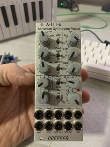
Doepfer A-111-6 Miniature synthesizer module, eurorack, VCO ADSR full voice
$ 88.7
- Description
- Size Guide
Description
Good working order, with no crispy knobs or any major defects, was used in an ambient setup for random tones. all input work, no bad switches. comes with eurorack cable.specs copied from Doepfer site. manual and calibration instructions available there.
VCO
triangle core VCO
frequency range: about 32 Hz ... 16 kHz
precise 1V/oct tracking: about 32 Hz ... 4 kHz
Tune:
manual tune control (with an internal jumper the range can be set to ~ +/-1 half an octave or ~ +/-2.5 octaves)
Oct.
: range switch -1 / 0 / +1 octave
Mod.
: modulation depth (attenuator wired to the
Mod.
socket)
Dest.
: switch that is used to address the modulation to frequency modulation (position
FM
) or pulsewidth modulation (positon
PM
), in center positon no modulation
PW:
manual pulsewidth control for rectangle waveform, PW can be also modulated by the Mod. input as mentioned above
Wave
: waveform switch (sawtooth / off / triangle), the sum of the waveform chosen by this switch and the rectangle is fed into the VCF (to turn the rectangle off the PW control has to be set fully CCW or fully CW)
1V/Oct.
(socket): external CV input for VCO frequency (1V/octave)
access to internal bus CV (via jumper, optional, please remove the bus jumper if this feature is not used to avoid unwanted frequency modulation as then the unused CV line of the bus works as a kind of antenna)
Balance unit
The balance unit is made of two VCAs which are controlled by the sum of manual Balance control and the balance CV input in the opposite direction.
The audio input of VCA1 is hard-wired to the VCO output, audio input 2 is connected to the socket Ext.In.
The output of the balance unit is used as audio input for the VCF
Bal.:
manual balance control, fully CCW the internal VCO is used, fully CW the external signal (Ext.In) is used,
at center position both signals have about the same level
CV Bal.
: CV input for balance (range about 0...+5V)
Ext. In
: external audio input for VCA2, about
5 Vpp level required for similar loudness as the internal VCO
this socket is normalled to the internal
VCO suboctave f/2
signal (rectangle with half the frequency), if no external signal is applied the suboctave signal is used as the second signal for the balance unit
VCF
24 dB low pass
Frq.
: manual frequency control
FM1
: frequency modulation depth (attenuator wired to the
VCF FM1
socket, the socket FM1 is normalled to the internal
Envelope
signal and then FM1 controls the modulation depth of the internal envelope applied to the filter)
FM2
(socket) : second CV input for VCF without attenuator (about 1V/octave), the socket FM2 can be normalled to the 1V/Oct socket of the VCO by means of an internal jumper, in this case the VCF frequency follows the VCO frequency (so-called
VCF tracking)
Res.
: manual resonance control (up to self oscillation)
if the VCO is turned off (waveform switch = center position, pulsewidth control = fully CCW or CW) and the VCF resonance is set to maximum the module can be used as a sine oscillator, the tracking at socket VCF FM2 is about 1V/octave (not as precise as the VCO but much better than most other filters)
~ 11 octaves frequency range (~ 10 Hz ... 20kHz)
access to internal bus CV for bus controlled VCF tracking (via jumper, optional, please remove the bus jumper if this feature is not used to avoid unwanted frequency modulation as then the unused CV line of the bus works as a kind of antenna)
VCA
Gain
: manual amplitude control (initial gain), can be used to open the VCA without envelope signal
VCA
(switch): used to switch between gate and envelope as control signal for the VCA, in center position the VCA is not controlled by envelope or gate, in this case the VCA loudness is controlled only by the manual gain control
note: when gate is used the VCA is controlled directly by the gate signal (i.e. hard on/off), this may lead to clicking noise under certan conditions (especially with low VCO/VCF frequencies), an
additional jumper is available that adds a bit slew to the gate signal when it is used to control the VCA directly, this avoids the mentioned clicks but lowers the rise and fall time of the gate signal (affects only the internal gate signal processing and has no influence to the applied external gat signal)
special control scale: exponential scale in the range from about -20dB to -80/90dB, linear scale from about -20dB to 0dB
Remark
: this special control scale results in a loudness behaviour that is a bit different from pure linear or exponential VCAs
Out
: audio output of the module (= VCA output)
Envelope
Gate
(socket): Gate input, level min. +5V/max. +12V, can be normalled to the bus gate signal by means of a jumper
Att
: manual control for Attack
D/R
: manual control for Decay/Release
Env.
(switch): used to switch between A/D, ADSR and A/R mode of the envelope generator, in center position (ADSR) the sustain level is fixed to about 50%
Envelope
(socket): envelope output (about +10V)
CVT
(socket): CV input for time control, by means of two internal jumpers one can select which time parameters are controlled by the CVT input (e.g. A only or D/R only or A/D/R) and in which direction (i.e. if an increasing CVT shortens or stretches the time parameter in question)
Envelope LED display
Attack time range: ~ 1ms ... 5 sec (can be extended by using the CVT input)
Decay/Release time range: ~ 1ms ... 15 sec (can be extended by using the CVT input)
